
The initial assessment of any lower extremity deformity is fundamental to plan a successful surgical program of correction, as well as an effective post-operative management of the healing process. The assessment should include the X-rays of full length weight bearing of both legs, with a complete axis evaluation to fix the position of the deformities, which is “the true plane of the deformity”.
Bone deformity is usually a combination of angulation and rotation. Coronal planes angular deformity (varus and valgus) is seen on AP radiographs, and sagittal plane angular deformity is seen on lateral radiographs.(1) This understanding of angular deformities is central to the correct use of an external device.
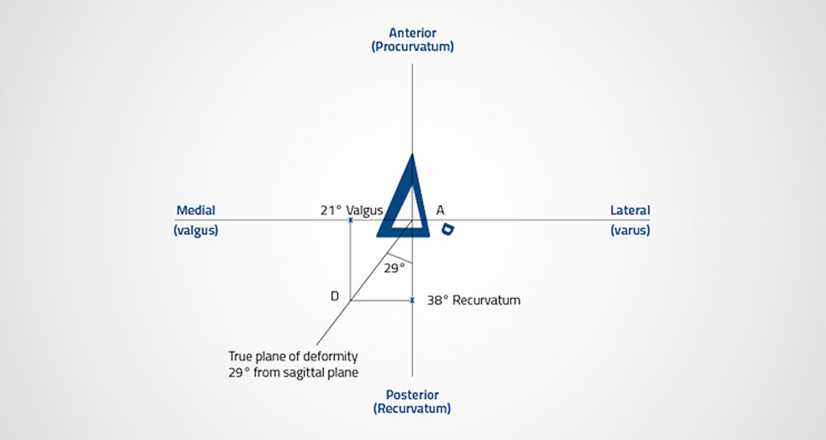
The graphical method of calculating the true plane of the deformity is a low-tech one: the only tools required are a pencil, a ruler, a goniometer and a graph paper. X and Y axis are marked with the center of the bone at the intersection with the abscissa – then anterior, posterior, medial and lateral positions are indicated. The grade of deformity is plotted on each axis to the same scale. For instance, a deformity that measures 21° degrees valgus on the AP rays is marked along the X-axis in a medial direction. S. Nayagam, an expert orthopedic surgeon from the University of Liverpool (UK), suggests a simple way to remember this: try to think of a valgus deformity as one with the apex pointing medially, and mark the size on the graph paper in the medial direction. Likewise, a recurvatum deformity that, for instance, measures 38° on the lateral X-rays is plotted in a posterior direction (recurvatum, apex posterior).(2) Orthogonal lines are drawn from these points so they intersect each other, and then a line is drawn from this intersection to the zero position. And this is the true plane of the deformity. The deviation of this plane from the sagittal and coronal planes can be established directly off the graph paper: if a millimeter-square graph paper is utilized, and the scale adopted for plotting is 1 mm to 1 degree, then the length on the line (AD) in millimeters, connecting the abscissa to the two orthogonal lines’ intersection, is the size of the deformity in degrees, and the angle that it subtends with both coronal and sagittal planes measures the true plane of deformity.
There is also a mathematical method for calculating the plane of deformity. In this case, the parameters can be measured trigonometrically from the known angles of the deformity in the AP view and lateral planes, as following: X is the AP (procurvatum/antecurvatum) angulation; Y is the varus/valgus angulation. The deviation of the deformity from the sagittal plan is X/Y° tan–1. The true plane of angular deformity is the plane in which the hinge of the fixator clamp should be placed. Other similar methods of estimation of the true angular deformity may be used, such as the rectangular rule.(3)
References
- Youngman J, Raptis D et al. 2015. An accurate method of determining a single-plane osteotomy to correct a combined rotational and angular deformity. Strategies Trauma Limb Reconstr; 10(1): 35-9.
- Patterson M (reviewed by) 2006. Apley’s Concise System of Orthopaedics and Fractures (3rd edn) by Solomon L, Warwick D, Nayagam S. Ann R Coll Surg Engl; 88(4):425-426.
- Jansen Paccola CA. 2011. A simplified way of determining the direction of a single-cut osteotomy to correct combined rotational and angular deformities of long bones. Rev Bras Ortop; 46(3):329-34.